
Views: 0 Author: Site Editor Publish Time: 2026-08-03 Origin: Site


Specifying the right high-performance polymer is only half the battle. Selecting the optimal stock shape dictates material yield, machining time, and ultimate part integrity. You simply cannot overlook this vital initial step. When engineering components for harsh chemical or thermal environments, PPS GF40 serves as an industry-standard choice. However, defaulting to the wrong profile often leads to excessive waste, accelerated tool wear, and compromised mechanical strength. The extrusion process naturally alters internal fiber orientation. This means each shape behaves quite differently under applied stress. In this comprehensive guide, we provide an evidence-based comparison of sheet and rod profiles. We examine crucial machining realities, structural considerations, and material waste factors in detail. Engineering and procurement teams will discover exactly how to confidently select the correct profile for their specific application.
Both profiles share the core thermal and chemical properties of glass fiber reinforced PPS, but extrusion methods cause distinct internal fiber alignments that impact part strength.
PPS GF40 rods are structurally optimized for CNC turning and cylindrical components like bushings and seals.
PPS GF40 sheets offer superior yields for flat, complex-milled components like manifolds and structural insulators.
Material yield calculations must account for the high cost of this PPS engineering plastic; selecting a profile closest to the final part dimensions minimizes waste and tooling costs.
Before diving into profile selection, we must first understand the foundational material. By definition, this polymer is a rigid, opaque PPS high temperature material reinforced with 40% glass fiber. Manufacturers compound the base polyphenylene sulfide resin with short glass fibers. This combination dramatically enhances structural rigidity and thermal resistance compared to unfilled grades.
Engineers consistently choose this material for demanding environments because it delivers exceptional reliability. You can expect several critical performance benchmarks:
Exceptional continuous service temperature: The material easily withstands continuous exposure up to 220°C (428°F) without losing significant mechanical integrity.
Near-zero moisture absorption: Unlike nylon or other hygroscopic polymers, it resists water uptake. This characteristic ensures exceptionally high dimensional stability in wet or humid environments.
Broad chemical resistance: It withstands aggressive exposure to industrial solvents, strong acids, and caustic bases. Few chemicals can degrade its matrix below 200°C.
Because the base resin remains completely identical across different shapes, your decision between a sheet and a rod does not rely on chemical or thermal data. Instead, the choice hinges entirely on manufacturing efficiency, specific part geometry, and directional strength requirements. Choosing incorrectly forces your machinists to mill away expensive material, which wastes money and rapidly destroys cutting tools. A well-planned profile selection aligns the stock shape closely with the final component footprint.
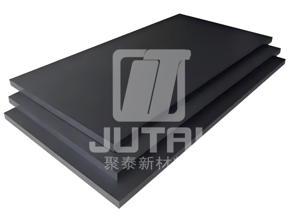
When your design features broad, flat surfaces or complex internal pocketing, starting from a flat stock profile is highly advantageous. A PPS GF40 sheet provides the ideal blank for multi-axis milling operations.
Sheets excel when the final component is planar, box-like, or requires extensive surface area. Machinists typically clamp these shapes directly onto CNC mill beds. Common applications heavily rely on the flat, stable nature of the sheet stock:
Fluid handling manifolds: Complex routing blocks requiring intersecting drilled channels and flat sealing faces.
Pump housings and wear plates: Structural covers managing high-pressure chemical flows.
Electrical insulators and structural supports: High-voltage separation barriers operating in extreme heat environments.
While sheets offer excellent milling yields, you must navigate specific material behaviors during fabrication. The manufacturing method used to create the sheet deeply influences how the material behaves on the machine table.
During the extrusion process, molten polymer forces its way through a wide, flat die. Glass fibers naturally align parallel to the direction of this extrusion flow. This physical reality creates anisotropic strength properties across the sheet. The material exhibits significantly higher tensile strength along the extrusion path compared to the transverse direction. When designing a load-bearing part, you must align the primary mechanical stress parallel to this internal fiber grain for maximum durability.
Residual stress remains a constant threat when machining extruded polymers. As the thick plastic sheet cools during manufacturing, the outer layers solidify much faster than the inner core. This differential cooling locks internal stresses into the material. Aggressive, asymmetrical material removal suddenly releases these stresses, inevitably leading to severe part distortion. We call this the "potato-chip" effect.
Best Practices for Sheet Machining:
Always utilize symmetrical machining techniques. Remove equal amounts of material from both sides of the sheet.
Rough out the entire part first, leaving a small finishing allowance, before taking final precision passes.
Specify stress-relieved sheets from your supplier if your part demands incredibly tight flatness tolerances.
For round, symmetrical components, turning operations provide the fastest and most accurate manufacturing route. A PPS GF40 rod acts as the perfect starting point for CNC lathes.
Rods perfectly match components requiring continuous outer diameters, internal bores, or threading. Holding a rod in a lathe chuck allows for rapid, concentric material removal. Typical applications leverage the uniform radial properties of the rod profile:
Thrust bearings and wear rings: Cylindrical supports managing high rotational friction.
Valve seats and high-pressure seals: Precision round inserts maintaining fluid barriers in chemical pipelines.
Rotary components: Specialized gears, bushings, and spacers used across aerospace and automotive systems.
Working with round stock introduces a different set of challenges. While milling focuses on flatness, turning focuses heavily on internal core integrity and concentric stability.
Rods undergo extrusion through circular dies. This process packs the glass fibers tightly along the longitudinal axis, while maintaining uniform strength radially from the center outward. This specific fiber distribution makes rods structurally ideal for parts subjected to rotational or hoop stresses. Whether you are pressing a bearing into a housing or subjecting a seal to internal fluid pressure, the rod profile provides the uniform radial resistance required to prevent premature failure.
Extruding large-diameter polymer rods presents a severe thermal challenge for manufacturers. Plastic acts as a natural thermal insulator. When a rod exceeds roughly 3 inches in diameter, the outer skin cools and hardens rapidly upon exiting the die. The deep inner core, however, remains molten for a significantly longer period. As this hot core eventually cools, it shrinks. Because the solid outer skin cannot collapse inward to compensate, the shrinking core pulls apart, creating microscopic voids or center-line porosity.
Common Mistakes to Avoid:
Machining a small, highly critical solid part from the exact dead center of a massive rod blank.
Ignoring internal void risks when designing high-pressure fluid seals that utilize the rod's core.
If your design absolutely relies on the center material of a large-diameter stock, you must request void-free, ultrasonically tested stock from your supplier. Alternatively, you can core-drill the rod early in the machining process to remove the porous center entirely if the final part is a hollow ring.
Making the correct choice requires a structured approach. You must weigh material yield, tool life, and structural load paths. We have developed an evaluation framework to help you navigate these competing priorities.
Machining generates scrap, and in the world of high-performance polymers, scrap represents lost budget. You must visualize the bounding box of your final part against available stock shapes.
Scenario A: Imagine milling a completely round flange from a square sheet. You will instantly generate massive corner waste. The machine spends valuable cycle time cutting away perfectly good material just to reach the circular profile.
Scenario B: Conversely, turning a rectangular manifold block from a large rod proves equally disastrous. The lathe must perform excessive, interrupted roughing passes. You destroy expensive carbide tooling to turn a circle into a square.
We cannot overstate the abrasive nature of a 40% glass fill. Glass fibers act like microscopic sandpaper against cutting edges. Minimizing the sheer volume of material you remove becomes critical to reducing insert replacement costs. Every extra cubic inch of material removed degrades the tool. Therefore, selecting a stock shape closely mirroring your final part geometry directly extends tool life. Polycrystalline diamond (PCD) tools perform best, but minimizing cut volume remains your best defense against wear.
You must evaluate the primary load path of your final application. Because extrusion aligns the fibers, the material is strongest parallel to the extrusion axis. Ensure your primary structural load runs parallel to the extrusion direction of your chosen profile. If a heavy bending force acts perpendicular to the fiber alignment, the part risks premature snapping. Discuss load vectors with your mechanical engineering team before finalizing the profile order.
To simplify the decision-making process, consult the following comparison table. It outlines the primary differences driving profile selection.
Feature Focus | Sheet Profile | Rod Profile |
|---|---|---|
Best Suited For | Flat, planar, box-like, or heavily pocketed parts. | Cylindrical, symmetrical, or threaded rotary parts. |
Primary Machine Strategy | Multi-axis CNC Milling Centers. | CNC Lathes and Turning Centers. |
Fiber Orientation | Aligned linearly along the extruded length of the plane. | Aligned longitudinally down the center axis. |
Primary Manufacturing Risk | Warpage from asymmetrical material removal. | Center-line porosity in large diameter stock. |
Tooling Strategy | Equal side-milling to relieve stress evenly. | Core drilling to remove center mass if hollow. |
Once you determine the optimal shape, the procurement phase begins. Navigating supplier catalogs requires an understanding of standard dimensional availability and industry compliance requirements.
Stock shapes do not come in infinite sizes. Manufacturers produce them in standard increments to streamline their own production lines.
Rods: These generally offer tighter incremental sizing. You can often find diameters in 1/8-inch steps. This granular availability allows buyers to purchase material exceptionally close to the net shape, driving down waste.
Sheets: Flat stock typically comes in standardized thicknesses (e.g., 0.5", 0.75", 1", 2"). If your final part measures 0.85 inches thick, you must purchase a 1-inch sheet and surface it down. This reality requires you to budget for the extra machine time needed to face the material.
When purchasing reliable PPS engineering plastic, documentation matters as much as the physical material. High-end applications in aerospace, medical, or fluid handling strictly require verifiable material origins. Always ensure your supplier provides proper lot traceability. Request material certifications guaranteeing compliance with standards like ASTM D4000 or RoHS. Operating without these documents exposes your project to severe liability if a part fails in the field.
Follow a systematic process to finalize your material order. We recommend a three-step mathematical approach to lock in your purchase:
Calculate the bounding limits: Determine the absolute bounding box (for milling) or bounding cylinder (for turning) of your final CAD model.
Determine workable margin: Identify the standard stock size that leaves approximately 0.125" to 0.250" of extra material on all sides. This margin gives the machinist enough room to clean up the extruded surface without causing excessive waste.
Compare required volume costs: Calculate the per-inch cost of the sheet versus the rod at that required volume. Factor in the estimated machining time to remove the excess margin.
Final Assessment: Ultimately, the choice between sheet and rod profiles is not a debate about baseline material performance. It is entirely a debate about manufacturing strategy. Because both shapes utilize the exact same high-performance resin, your decision dictates how efficiently your machine shop can produce the final component. Aligning the stock profile closely with the specific machining process—milling flat parts from sheets and turning round parts from rods—minimizes expensive material scrap. It also aggressively protects your cutting tooling from the abrasive glass fiber matrix.
Next Action: You should immediately review your part geometry and structural load requirements with your lead machinist or manufacturing engineer. Run the bounding box calculations to determine optimal material yield. Once you align on the geometry and grain direction, contact your supplier to request a targeted material quote for the most efficient profile.
A: Yes, in terms of baseline resin, but structural strength is directional. Glass fibers align differently during sheet versus rod extrusion, meaning mechanical strength varies depending on the axis of the applied load.
A: While possible, it is highly inefficient. It results in poor material yield, excessive tool wear due to the abrasive glass fibers, and longer cycle times compared to starting with sheet stock.
A: Use sharp, polycrystalline diamond (PCD) or carbide tooling, take equal cuts from both sides of the sheet to balance stress, and ensure the material is adequately cooled during machining.
A: It can occur in larger diameters due to the cooling process of thick cross-sections. If your part relies on the exact center of a large rod, request void-free or ultrasonically tested stock.


